How To Select Power Amplifiers For High-Frequency Millimeter Wave Applications
By Mike Lee, dB Control
For systems designers, selecting power amplifiers that can operate in the Ka-band, Q-band and other high-frequency bands is far more challenging than choosing amplifiers for lower frequency applications. Decisions and compromises that affect size, weight, and power, as well as costs (SWaP-C), become more impactful.
The complexity of designing systems for satcom, radar, electronic warfare (EW), electronic attack (EA) and electronic counter measures (ECM) is also increasing. For example, some of the most significant threats are now from missile seekers operating in millimeter wave (mmW) frequencies. These air-to-air and anti-ship missiles, as well as anti-tank guided missiles, use mmW seeker modes during their terminal guidance phase. This drives new requirements for mmW jamming performance in airborne, naval and ground vehicle systems.
This article examines some of the challenges inherent in finding reliable power amplifiers that work in high frequencies such as Ka-band (continuous wave and pulsed) and Q-band. It also details how SWaP-C and lead time challenges can be overcome, dispels a few misconceptions about operating in these frequency bands, and addresses systems designers’ diverse specification needs.
SWaP-C and Lead Time Challenges
The Ka-band comprises 27 GHz to 40 GHz and includes both a commercial band and a military band. It mainly is used for satellite communications because its focused spot beams allow frequency reuse to boost satellite system capacity.
The Q-band, meanwhile, comprises 36 GHz to 46 GHz and has been applied to satellite communications, radio astronomy studies, and automotive radars, and more. One of the Q-band’s major applications is Advanced Extremely High Frequency (AEHF), a secure, satellite-based military communications band. Here are some of the SWaP-C and lead time challenges that must be addressed:
- Size – It becomes more difficult to build products as you progress to higher frequencies because the components (e.g., waveguides and output devices) get much smaller. While SSPAs are starting to find a home in high-frequency applications, TWTs remain the more commonly used output device. However, building a TWT is labor-intensive and requires precise machining, all of which becomes more difficult as the size is reduced.
- Weight is a balancing game. Output devices and components get smaller and lighter as the frequency gets higher. When components shrink to fit in tighter spaces (e.g., manned or unmanned aircraft), their mass typically drops as well. However, as the frequency goes up, so do the operating voltages. Therefore, the size and weight of the power supply needed to drive the output device increases.
- Power likely presents the greatest design challenge since, as you go higher in frequency, it’s harder to generate greater power output. Even jumping from the Ka-band to the Q-band is a significant leap. This is partly because of atmospheric obscurants. As you operate higher in frequency, adverse environmental conditions such as rain fade increase — meaning the environment causes an increasing amount of attenuation. So, if you transmit 100 watts through the environment, you may only achieve a fraction of that because the signal is being attenuated through the atmosphere. Operators need sufficient power to establish a link plus enough power to persevere through atmospheric interference or risk losing communications and critical data or video transmissions.
- Linearity isn’t part of the SWaP-C acronym, but it should be when talking about amplifiers. Linearity is measured in spectral regrowth, intermodulation, or noise power ratio (NPR). At higher frequencies, it is more difficult to maintain a unit’s power level at the point of linearity, wherein one watt of input power leads to one watt of power output. When running in a linear region, a unit does not experience distortion at the outer frequencies, i.e., damaging nearby communications with your signal. While many satcom amplifier applications use the terms P1dB and linearity interchangeably, the terms do not mean the same thing. P1dB, also called the 1 dB compression point, is the output power level at which gain decreases 1 dB from its constant value (i.e., backed off 1 dB from the theoretical linear power level). It is not a good indication of linearity. Once an amplifier reaches its P1dB, it goes into compression and becomes a non-linear device, producing distortion, harmonics, and intermodulation products. A P1dB spec or figure of merit is catered more towards a solid state device, versus a TWT device.
- Cost – Ultimately, the combination of high-power requirements, labor-intensive manufacturing, and a small package makes up the leading-edge technology in these applications, which makes solutions more costly than similar units operating in, for example, the C-band or Ku-band. Some customers unfamiliar with the complexity of higher frequency components may experience sticker shock upon seeing a cost number that’s usually about double what they’ve seen at lower frequencies — depending on whether the application is in radar, communications, or other forms of transmission.
- Lead Time is also not in the SWaP-C equation as it isn’t always important. For military applications where an advanced system can save lives, it is definitely a prime consideration. The complexity of producing smaller components for high-frequency applications generally increases lead time. At lower frequencies, TWTs are built and manufactured at larger sizes, so deadlines are easier to achieve. As the components get smaller, it is not only harder to construct each component, but fallout increases, which decreases yield. In some cases, you may have to build several devices to achieve one good unit. Considering that the lead time for a travelling wave tube used in a Ka-band amplifier, for example, is anywhere from 25 to 50 percent longer than that of a lower frequency unit, lead time can become a critical factor in your choice of device that can operate at high frequencies and produce the required output power.
New GaN Solid State Amplifiers Help Meet mmW Challenges
While the most mature amplifier technology for jamming applications in the mmW bands is the TWT, GaN solid state amplifiers (SSA) are being used in ECM and EA programs in frequencies from 20 MHz up through 6 GHz, and even in applications up through 20 GHz. GaN SSAs are particularly well suited for communications jamming where most applications are below 6 GHz, and GNSS jamming around 1.2 to 1.6 GHz. The deployment of 5G networks for military applications is also driving EW requirements for Frequency Range 1 (450 MHz to 6 GHz, which includes the heavily used 3.3 to 3.8 GHz range) and Frequency Range 2 (24.2 to 54.6 GHz).
Benefits of Amplifiers Designed for mmW Applications
Millimeter-wave (mmW) technology provides much higher bandwidth, increased connectivity with more channels and faster exchange of data during tactical communication. Amplifiers for mmW applications must be equipped to operate in complex applications and endure harsh environments (extreme temperatures, excessive vibration, and altitudes of 50 thousand and even 70 thousand feet above sea level).
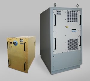
dB Control is known for its mmW amplifiers because we incorporate reliability from the initial design phase. Plus, our design and test engineers and our manufacturing technicians are specifically trained to work with high-voltage electronics. The result is an outstanding track record for producing reliable mmW high-power products for airborne, maritime and ground mobile deployments. We offer six TWT amplifiers, three microwave power modules, and two GaN solid state amplifiers designed to meet the demanding requirements of mmWave applications: Please visit dB Control’s mmWave products page for more information, or download the product data sheet of the amplifier listed below that meets your frequency and power requirements:
- 2.9-3.3 GHz, 1.5 kW GaN SSA (dB-8048)
- 2-18 GHz, 200W Pulsed GaN SSA (dB-8015)
- 17.5-40 GHz, 40/50W TWT Amplifier (dB-4051A)
- 18-40 GHz, 50/60W TWT Amplifier (dB-4051)
- 26.5-40.0 GHz, 125W MPM (dB-3201)
- 27.5-31.0 GHz, 200W MPM (dB-3202)
- 30.0-38.0 GHz, 125W MPM dB-(3201H)
- 32.0-36.0 GHz, 400W TWTA (dB-3861)
- 34.5-35.5 GHz, 700W TWTA (dB-3709i)
- 34.5-35.5 GHz, 750W TWTA (dB-3860)
- 34.5-45.5 GHz, 80W MPM (dB-3205)
COTS or Custom?
If you’re considering using commercial off-the-shelf (COTS) units or custom components, let the application be your guide. Excellent amplifiers are available off the shelf, but most operate at fairly standard frequencies. Customization becomes relevant when you need more power, a slightly higher or lower frequency, a broader bandwidth, or guarantees for a certain linearity.
Custom orders require an understanding of the “stat weight” afforded to different unit specifications within the user’s application. First, the vendor has to offer the frequency range and the power needed. Other parameters then vary. For example, in a satcom application, linearity is a concern. In ECM, EW or radar applications, weight and efficiency is important when the system will be mounted on an airborne platform.
Conclusion
Choosing an amplifier to incorporate into a system designed for mmWave applications such as satcom, radar, EW and ECM is challenging. It’s easier if you work with an experienced amplifier manufacturer. dB Control has been building Ka-band amplifiers for 18 years and provided products for military applications for 34 years. In that time, we’ve become proficient designing and building modulators, as well as integrating them into our solutions (i.e., to handle pulsed wave applications, such as radar, or some EW tasks). We wind our own transformers – a vital component of high-voltage power supplies – and use proprietary methods and materials in the encapsulation of high-voltage system sections.
We understand custom application demands, such as ensuring that an amplifier can operate at 50,000 or even 70,000 feet and perform reliably in both pressurized and non-pressurized aircraft cabins. That’s why every dB Control product, from the component level and sub-assembly level all the way up to the amplifier level, is subjected to environmental stress screening before it is shipped. While many vendors perform environmental stress screening, none also offer in-house transformer winding plus full encapsulation, nor have the experience to execute the appropriate testing and ensure the tightest of electrical tolerances specified down to the component level.
At its core, dB Control is an amplifier manufacturer specializing in high-voltage power supplies. Another difference between us and our competitors is that we’re output-device agnostic – we offer both TWT and GaN solid state amplifiers. This gives us a wider range of solutions we can use to meet your specific requirements. Plus, we’re the only manufacturer that can cover the full 2 to 40 GHz spectrum in two devices (dB-8015 and dB-4051 or dB-4051a). If you need help choosing the most viable amplifier solution to meet your specifications and perform reliably in challenging environments, please email the author, Mike Lee, or visit dbcontrol.com.
About The Author
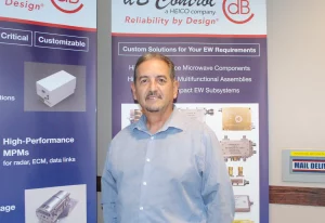
 Mike Lee is Vice President of Sales and Marketing at dB Control. He has more than 25 years of RF and microwave experience developing new relationships with companies whose specs require high-power TWTAs, MPMs, power supplies, contract manufacturing services or repair depot services. Prior to joining dB Control, Lee worked at Comtech Xicom Technology and IBM – where he received a U.S. Patent for his electrical circuit design. He earned a Bachelor’s of Engineering in Electrical Engineering from The City College of New York.
About dB Control
Established in 1990, dB Control supplies mission-critical (often sole-source) products worldwide to military organizations, major defense contractors, and commercial manufacturers. The company designs and manufactures reliable high- and low-voltage power supplies, high-power TWT Amplifiers (TWTAs), microwave power modules (MPMs), transmitters for radar, electronic countermeasures (ECM) and communication applications on airborne, maritime, and ground-based military platforms. After acquiring TTT-Cubed in 2019, Paciwave in 2021, and Charter Engineering in 2022, dB Control expanded its product line to offer coaxial EM and pin diode RF switches, specialized RF/microwave components, integrated microwave subsystems, and custom radio frequency (RF) receivers and sources. dB Control also provides specialized contract manufacturing and repair depot services from its 40,000-square-foot facility in Fremont, California. The company is AS9100D and ISO 9001:2015 certified. More information is available at www.dBControl.com or by calling 1-510-656-2325.
This article How To Select Power Amplifiers For High-Frequency Millimeter Wave Applications was published by rfglobalnet.com on July 1, 2024.

